Here are some of my SB-200 notes...
Robert Norgards KL7FM's, notes on upgrading the Heathkit SB-200
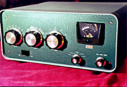
About two years ago, I purchased a used Heath SB-200 amplifier. It came unmodified, but included the Harbach power supply kit, Soft-Start kit, a new fan and relay. I had a good time putting in these items, most of which were sorely needed. During this time I also added several other mods which seemed appropriate. Some were found at Rich Measures website, others were mine. All improved the operation of the amplifier.
The following notes were made when I put together a kit of parts for a friend of mine who wanted to modify his Heath SB-200 amplifier as I had when I rebuilt mine. I did not write this document for any purpose other than to help out a friend. Perhaps some of it may be of use to you.
SAFETY FIRST
Caution: When servicing your Heathkit SB-200 amplifier, make sure the AC cord is un-plugged. Also, be aware that a high-voltage may be stored in some power supply capacitors. When in doubt, temporarily short the capacitor terminals with a short piece of insulated wire. Never plug in the amplifier with the RF cage open. Extremely lethal voltages are also present in the amplifier under-chassis when the unit is plugged in, even if it is not turned on. In short...BE CAREFUL!!!
Tip: It is helpful to tie a colored string through the holes in the AC power cord pins, or put tape around the pins while working on the amplifier. In this way, you avoid the possibility of accidentally plugging in the amp while you are working on it. This can easily happen if you grab the wrong cord to plug in a piece of test equipment, etc., while working on the amplifier.
HV Glitch Resistor (10 Ohm, 10W glass) (Note 1)
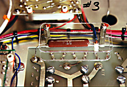
Purpose - This resistor protects the power supply capacitors, diodes, etc. in the event of a high-voltage "glitch". If anything inside the RF cage should short the +2400 volt buss, and this includes a tube short, bypass capacitor short, mechanical short, bug crawling in there, small piece of wire, etc, falling through the vent holes in the top of the amplifier, etc. If any of this happens, some components in your power supply may become damaged. This resistor attempts to limit this peak current. Since there is the possibility this resistor may self-destruct in protecting the power supply, it is mounted between two Lexan(tm) shields.
Installation Overview -
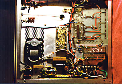
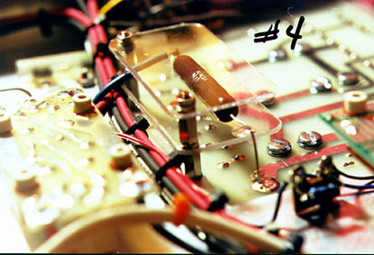
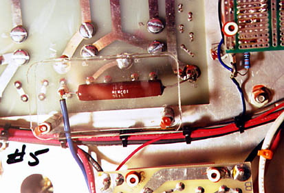
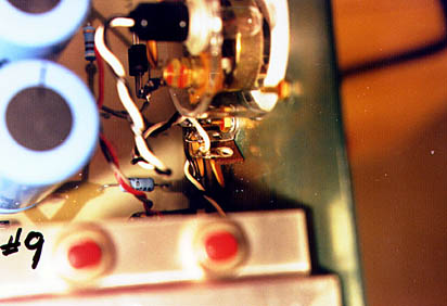
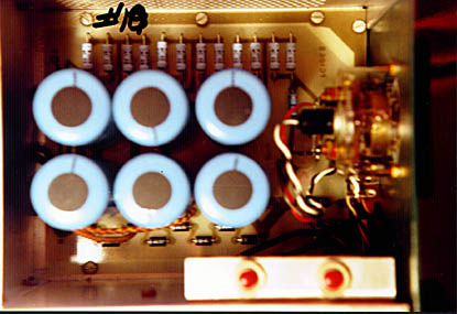
For this operation, the amplifier should be upside-down, with the rear of the chassis nearest you. Compare your view of the amplifier chassis with photos 1, 3, 4, 5 and 6. Also, you may refer to Heath pictorial 6. You will be removing the (Large Blue Wire) which is soldered to the lower-left of the power supply board. The large blue wire traces a path from this point up and to the left, finally being routed through a grommet into the RF cage.
Installation Steps:
* Remove the amplifier chassis from the exterior cabinet.
* Remove the screws holding the top of the RF cage. Set these items aside. If any of the screws had a loose fit from stripped holes, they should be replaced with a larger screw. Hex-head #8 x 1/4" sheet metal screws are ideal.
* Turn the amplifier upside-down, with the rear facing you. Compare your view of the amplifier chassis with the photos enclosed. The power supply circuit board is located in a rectangular chassis cut-out in the right half of the amplifier chassis.
* Unsolder the LARGE BLUE WIRE from the lower-left of the power supply circuit board. This is the same wire identified in the Installation Overview for this component.
* On the left side of the cut-out, remove two #6 nuts on the screws holding the power supply circuit board to the chassis. Discard the nuts. Leave the lock-washers in place.
* Install a threaded stand-off in place of each nut removed. Tighten.
* Install the Lexan shield with the resistor mounted on it on these standoffs. The free end of the resistor will be towards you.
* Install two more standoffs onto the studs just installed, thus holding the lower resistor and shield in place.
* Solder the blue wire removed from the circuit board to the terminal on the resistor guard. (S2)
* Bend a small loop (1/8") in the free end of the resistor. Make a gradual 90 degree bend in the resistor lead and solder the loop to the circuit board where blue wire was previously removed.
* Install the upper Lexan resistor guard on the studs, and secure with nuts or screws supplied.
* End of procedure.
Diode Protection for R12 (3 ea. 1N5408 Diodes in Series) (Note 1)
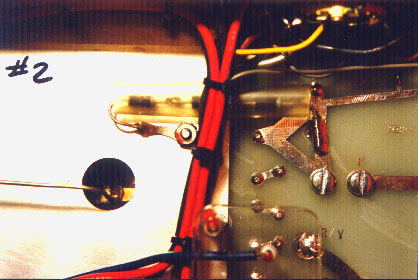
Purpose - During a high-voltage event, a large current will flow through R12, possibly damaging it. If the resistor opens, a high-voltage pulse would also travel through the meter if set to the "plate" position. Three series diodes are added in parallel with R12 with anodes toward ground. These diodes will clamp the voltage developed across R12 to approximately 2.1 volts.
Installation Overview - Refer to photo 2, for details. You will have the amplifier in the same position as when installing the HV glitch resistor. This is a new component install.
Installation Steps -
* Orient the chassis upside-down, with the rear towards you, the same as in the resistor installation above.
* Refer to photo 2. Remove the #6 nut and lock-washer located just above and to the right of the chassis hole. You may have to put the amplifier on it's side for this operation, as the screw will have to be held with a long screw driver. Always set the amplifier on it's side with the transformer down. There is a danger the unit will tip over if you do not.
* Install the diode assembly over this screw and replace the lock-washer and nut. The diode assembly will be located under the wiring harness as shown. Tighten the nut.
* Note the position of the other end of the diode assembly in the photo. It will be soldered directly to the circuit board foil just above the left capacitor screw. You may have to bend the lead slightly.
* End of procedure.
New Value for C10 (.0025 uF, 10 kV) (Note 1)
Purpose - Improved bypassing at 80 meters. The existing value for this capacitor is .001 uF at 3 kV. Increasing the value to .0025 uF decreases the reactance by 2.5 times. Less RF will leak back into the power supply.
Installation Overview -
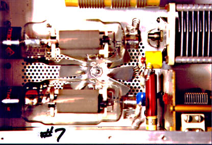
The install amounts to removing the existing component and installing the new one. A new rubber grommet is included also. You may as well put in the new one. Refer to photo 7, where you will see the new capacitor, blue in color. The detail is better shown in Heath pictorial 9.
Installation Steps -
* With the amp right-side up and the tubes removed, compare what you see to Heath pictorial 9.
* Remove the blue wire and one side of the .001 3kV capacitor from lug 1 of RF choke AN.
* Remove the .001 3kV disk capacitor from solder lug E.
* Replace the existing rubber grommet at hole F with the new one.
* Install the new .0025 10kV blue capacitor between lug 1 of RF choke AN(NS) and solder lug E(S1).
* Replace the blue wire at lug 1(S2).
* Check that the solder connection at lug 1 of the RF choke AN is not shorted to ground. This point carries over 2,200 volts.
* End of procedure.
VHF Low-Q Suppressor Assembly (New PC1, PC2) (Note 1)
Purpose - This new VHF suppressor assembly has more than twice the suppression capability of the old one. The coils are wound of 18 ga. Nichrome wire, and the resistors are 100 ohm 3 watt types. Also, notice that the coils all have their axis oriented 90 degrees from each other. This is so that coupling between coils is kept to a minimum. Built into this assembly is a fifth resistor which acts as a protection fuse. This one-ohm resistor replaces the solid wire jumper from the RF choke AN to the 1000pf "door knob" capacitor at AP (Ref. Pictorial 9). The new suppressor assembly starts working at just above the 10 meter band. It actually has some effect on power output at 10 meters. You will probably notice a slight output drop at 10 meters from what you have come to expect. This small loss of output at 10 meters is the price you pay to make the amplifier resistant to VHF oscillations. The resistors themselves may heat considerably in operating at 10 meters, and after some time, they will become discolored. This is normal. Silver solder has been used in it's assembly. This type of solder is 50% stronger than regular 60-40 solder, and melts at a higher temperature. I made these suppressors from components and instructions obtained from Rich Measures website.Installation Overview -
The installation is quite simple. I have drawn arrows on the tops of the plate connectors pointing toward the tubes. The one-ohm resistor points down. The suppressor assembly has already been trial fitted in my amplifier. It fits perfectly. Except for some slight bending required as the tubes are installed, everything is "shaped" properly.
Installation Steps -
* The amplifier should be prepared as in the previous component install. These steps begin where the previous ended.
* Refer again to Heath pictorial 9. Find the orange highlighted wire running from lug 2 of RF choke AN to point AP on the 1000pf "door knob" capacitor. Cut this heavy wire jumper in the middle.
* Remove the screw at AP which holds the old suppressor assembly to the door knob capacitor. Save this screw. You may also want to save the old suppressor which contains the hard-to-find plate cap connectors.
* Unsolder the remaining half of the heavy wire jumper from lug 2 of RF choke AN. Clean up the solder lug.
* Take your time installing the new assembly. Hold the new assembly so that the two arrows point towards where the tubes will be. The free lead of the smaller, 1-ohm resistor should go through lug 2 of RF choke AN. Hold off on soldering this until after the suppressor is completely positioned.
* With the resistor lead now in the solder lug, position the mounting lug of the assembly over the door knob capacitor, and use the old screw to secure it. You may have to hold the capacitor while tightening this screw.
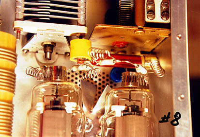
* Refer to photo 7, and photo 8. Unfortunately, the 1-ohm resistor is not visible. When everything looks correct, dress up the resistor lead on lug 2. Cut off the excess wire, and solder S1.
* If you have a new fan assembly, now would be a good time to install it as long as the tubes are out.
* Before replacing the tubes, wipe them off with some glass cleaner. Finger prints on the tubes cause hot spots.
* End of procedure.
Extra Meter Lamp Bypassing (2 - .02 uF disk capacitors)
Purpose - The 6.3 volt transformer winding runs the whole length of the underside of the amplifier compartment. The underside is "hot" with RF when transmitting. The wires for the meter lamp pick up some stray RF and re-radiate it through the meter hole in the front chassis. I may be reaching for straws here, but it can't hurt.Installation Overview -
There is a three terminal solder strip next to the meter where the lamp wires are spliced to the wiring harness. This is where the two added capacitors will mount. Depending on your dexterity with needle nose pliers and soldering iron, you may not have to remove the front panel.
Installation Steps -
* Take the two .02 capacitors and cut off the leads to 3/4". Bend small hooks at the ends of the leads.
* Look at the existing 3 terminals on the strip. The center one should be empty. Refer to photo 9 and photo 10, and again to Heath pictorial 9. I have made an extra sketch to show how the added capacitors will mount. This one is pretty much self-explanatory.
* After the capacitors are mounted, it should be: S3 on terminal 1, S2 on terminal 2, and S3 on terminal 3.
* Be careful to clean up anything you drop down in there. Remember, you're working right above the power supply board.
* End of procedure.
Input Damping Resistor (10 Ohm, 3-W) (Note 1)
Purpose - Adding a 10 ohm resistor to the cathode input of the 572-B tubes will accomplish two things. First, it adds 10 ohms of resistance to the VHF feedback signal path, thus helping to damp VHF oscillations. Second, it reduces the tendency to over drive the amplifier. A pair of 572-B's will require only 50 to 65 watts of drive for full output. More drive just causes the signal to "flat top" and splatter.
Installation Overview -
For this job, you will be simply removing a jumper wire and installing a resistor.
Installation Steps -
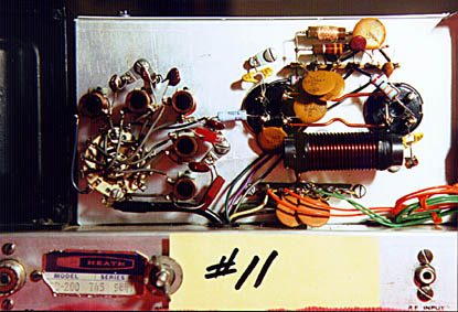
* Take a look at Heath pictorial 10, along with photo 11 and photo 12. On the pictorial, find the wire running from lug C6 of switch wafer AK, and terminal 2 of socket V2. Cut this wire just to the right of coils CC and CD. Cutting the wire makes it easier to remove. Remove both pieces.
* The 10 ohm resistor included has a length of gray wire connected to one end. The other end is bare and cut to about 1/2". Connect the short bare end to lug 2 of socket V2 and solder.
* Cut the insulated gray wire on the resistor to the correct length and strip it back about 1/4". Tin this end and connect it to lug C6 of switch wafer AK and solder.
New C14 & C15 (4 - 470pf, 1KV)(Note 1)
Purpose - To decrease the grid-to-ground reactance. Better efficiency at the lower bands should be the result. (Note 1)
Installation Overview -
This is also an easy one. There are two points to work on, and for these you should refer to Heath pictorial 11 and photo 12. At each of the two places you will be removing one 200pf capacitor and installing two 470pf capacitors. So, just as you can see from the pictorial, you will be removing two caps, and installing four.
Installation Steps -
* Remove the 200pf capacitor mounted between lug AD and lug 3 of socket V2.
* Install two(2) 470pf capacitors between lug AC and lug 3 of socket V1.
* Remove the 200pf capacitor mounted between lug AC and lug 3 of socket V1.
* Install two(2) 470pf capacitors between lug AD and lug 3 of socket V2.
* End of procedure.
Safety Spacers for Step-Start Board (4 Plastic Spacers)
Purpose -
If you installed the Harbach Electronics Step Start circuit, you were told to mount it with silicone rubber/sealer. This is good. It will in all likelihood never come loose from the chassis. But for about 15 cents worth of insurance, you can make it so that even if it does come loose, it will not hurt anything.
Installation Overview -
You will need the four small white plastic spacers, and a tube of GE or other silicone rubber.
Installation notes -
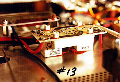
* Refer to photo 6 and photo 13.
* Using a small dab of silicone rubber glue, fasten the 4 spacers to the circuit board in the positions shown. When positioning them, try to keep them either on a circuit trace, on the blank board. Try not to bridge traces with the glue.
* End of procedure.
Now, if for any reason the board does come off, it will merely rest on these spacers. Nothing will short to the amplifier case.
Additional Notes:
Check D18
At this time, it would be a good idea to check a few things in the area. Notice diode D18. See photo 12 and pictorial 10. Check it with your ohm-meter. It should read high one way (open), and low in the other direction, (about 700 ohms, depending on what kind of meter you have and the range setting). If this diode checks bad, i.e. open both ways, or is shorted both ways, there is a spare included with the parts kit. Inspecting the photo, you will see that the band is to the right. The replacement diode is an NTE177. This is the ALC rectifier. If this diode is bad, your linear will not put out the correct ALC voltage to the SB-102. It may cause you to over-drive the linear.
Check R21 & R22
Refer to Heath pictorial 10. Look at the two 33 ohm resistors (orange, orange, black). I have included two new 33 ohm 2%, 2W resistors to replace your existing ones if they are bad or out of tolerance. Measure yours. You can measure them in the circuit. They should measure 33 ohms +/- 4 ohms. If they read over 40 ohms, put in the new ones. One of them has a small capacitor tacked to one of the leads, so be careful here. Also, if they look a little off color in the middle like they have been overheated, be suspicious of them. They are 1W resistors, the new ones are 2W, but about the same size.
Capacitor C3 and C19
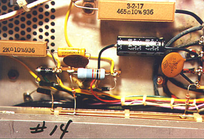
There are two small electrolytic capacitors that you may want to replace, or just keep them for spares. Looking at photo 14 and pictorial 7 will show you where they are. Be sure to observe polarity. There's a bit of teflon sleeving in the parts kit. Use it where you need it.
Resistor R15
In going over the circuits of the SB-200, I noticed that Heath should have used a 1.4 ohm resistor at R15. This resistor is the one used to get the grid current readings. Admittedly, it is a small point, and the bother surely does not justify the accuracy gain, but I have included a 1.4 ohm resistor in the kit, should you want to replace R15. A 1.5 ohm resistor was probably used because of availability. They are hard to find.
Diode Protection for R15
If you go to the trouble of replacing R15, install one of the 1N5408 diodes in parallel with it. This is easily seen on my photo 14. Note the direction of the band on the diode. R15 is barely seen just below the diode. I also drew in the diode for you to see in pictorial 7.
Diode Protection for Meter
You have probably done this already. It is a good idea to put two diodes, in parallel, with the polarities opposite, across the meter terminals. This will limit the maximum voltage that would appear across the meter to about .6 volts. Better than trying to find a new meter.
The FAN installation
If you have not installed the Harbach fan option until now, read this. Harbach suggests that you cut the leads off the old fan at the motor, then use two supplied wire nuts to hook up the new one. This is a quick and dirty fan replacement, and it works fine. But, I wanted it to be a little more professional. The leads on the new fan are quite long. In fact, they reach where they're supposed to go without using the old fan wires at all. Here's a hint: Cut the wires off the old fan, close to the fan. Now, instead of using wire nuts to connect the new fan, gently pull the fan wires out of the wiring harness. Use needle nose pliers, and just work them out backwards. When you get to the lugs where they are soldered you will know where to hook the new fan wires. Take a look at my photo 1 and photo 5. Doesn't show you where they land, but gives you an idea of how the wires are routed.
The Soft Key Circuit
You probably noticed an extra circuit board in my amplifier that you couldn't identify. Look at photo 1. In the lower right quadrant, just above the screw terminal strip where the AC power connects. The circuit board with the two white "S" shaped jumpers on it. That's my own soft-key circuit. It works the same as the Harbach unit, but gets it's power from a separate supply. Also, instead of 1.2 volts used for keying, mine puts out 10 volts at 10 mA. If yours is in and it works fine, leave it alone.
Filament Voltage Reduction(Note 1)
Overview -
I don't know whether I should get into this or not. Oh, what the hay. Look at photo 11 and photo 12. Notice the two coils of orange and green wire. Notice also the slightly different terminal strip located just under the filament choke where the orange and green wires land. Those two coils are dropping resistors. They reduce the voltage to the filaments.
Here's what I'm doing: The 572-B tubes recommended filament voltage is 6.3 VAC +/- .3 VAC. This means that the tubes should put out full rated power with 6.0 volts on the filaments. When I measured mine, they had 6.76 volts on the filaments. This was more than the maximum recommended voltage. Eimac did a study and found that for every 3% above the minimum filament voltage required for full output reduced tube life by half. That could, in fact, be why I'm not getting as much power out of mine as yours. The heaters are getting weak. You probably don't have much time on your tubes. That's why you've got the extra power.
It's hard to find resistors to do the job. Each tube draws 4 amps filament current. That's 8 amps total. Each of the two coils of wire is about 30 inches long. They're made of 22 ga. teflon wire. The resistive coils drop the extra voltage for me. I started with two 36 inch lengths and kept shortening them until I measured about 6.05 to 6.1 volts at the tube sockets. When I got the length right, I just coiled them up and hold them down in the corner with a stick-on and a ty-rap.
The reason I changed terminal strips was to give me two extra lugs. I had a 6 lug terminal strip, so I used it and had one lug left over. You can see that in the photo. What I did was hook the transformer filament windings to the outside lugs, and from those I put in my two dropping resistor wires. I also added a couple extra .02 caps to bypass the coils, since they probably pick up a bit of RF.
Before you start this, you will need to have the amplifier in working order. Make sure you have the amplifier sitting on an area of your bench where there is no danger of shorting something to the underside of the chassis. Remember: There will be 2200 VOLTS WAITING TO GET YOU under there. THE RF CAGE MUST BE IN PLACE AND FASTENED SECURLY. The outer case must be off of the amplifier.
Set the amp with the rear facing you. Don't connect anything to the rear of the amplifier. For this test, we will only turn the amplifier on and take one voltage measurement. If you have a set of clip leads, you may want to clip lead your meter to the test points first. Set your meter to read AC volts, and pick a low AC scale, as you will be reading about 6.3 volts AC. Connect the meter leads to lugs 1 and 4 of socket V2. See pictorial 11 for this. By the way, it would be very good if you had a digital reading meter for this. When you are set to read this voltage, turn on the amplifier. The voltage will gradually decrease a few milli-volts over the first minute or so. Take the reading after one minute. If your reading is more than 6.3 volts, I would take steps to reduce it. As you can see from the readings I got, mine was a very "HOT" transformer.
Now, how much wire to add. The wire I supplied will drop about 10 milli-volts per inch. So, take the voltage reading you just got and subtract 6.00 from it. Here is an example:
You read: 6.76 Subtract: 6.00 You get: 0.76
Divide this by 0.01: .76 / .01 = 76
You need 76" of wire. But, half goes in each leg, so that's two pieces 38" long.
So... for the above example, you need two coils of wire 38" long. The wire will heat slightly when in use, and in so doing will increase in resistance, dropping more voltage. To compensate for this, use about 8% (4") less wire. Use two pieces about 34" long. Of course, you will have to figure this out with the voltage reading YOU take.
I actually changed my terminal strip for the modification. There are other ways to do it besides changing the terminal strip. There is enough room to add a new mini terminal strip at the position shown in pictorial 11. This is the method I will now describe.
Installation Steps -
* Take the voltage reading and figure the required amount of wire, as outlined above.
* Make sure the amplifier is disconnected from the power line. Remove the RF cage cover again.
* Mount the new mini terminal strip. Refer to pictorial 11 where I have drawn in the new terminal strip. Try to mount it close to the position shown. It will require drilling a small hole for the #2 mounting screw. Use the supplied hardware.
* Replace the top of the RF cage.
* Remove the long and short green transformer wires from terminal strip M. Leave the rest of the wires on this strip in place.
* Connect the wires removed in the above step to the new terminal strip. One wire to lug 2. One wire to lug 4. (Lugs numbered 1-5 starting at top)
* Connect a .02 disk capacitor to lug 2 and 3.
* Connect a .02 disk capacitor to lug 3 and 4.
* Connect one end of new orange wire to lug 2. S3
* Connect one end of new green wire to lug 4. S3
* Solder also the two disk capacitors at lug 3. S2
* Tack solder the other end of the orange wire to lug 3 of terminal strip M.
* Tack solder the other end of the green wire to lug 1 of terminal strip M.
* Power up and take the voltage reading again. You should have a reading of between 6.0 and 6.15 volts. If not, adjust wire length again, and re-solder the connections permanently.
* End procedure.
RFI Suppression -
I have enclosed a snap on RF choke. The core is in two parts and is held together by a plastic enclosure. To make it easier to use, just snap it apart and wind the wire on it and replace the plastic holder.
I tried using this on my computer speakers. Here are the results obtained. My computer speakers were picking up RF from their power supply wires. I wound the wire coming from the cube power supply (wall-wart) around the core at least 10 times. Here, more turns is always better. Before I used the choke, when I talked over the radio (antenna about 6 feet away, 100 watts) I could hear myself in the speakers. After the choke was installed, the interference was still there, but I had to turn up the volume all the way to hear it. Great improvement. More improvement was noted in using the choke on the power lead to the speakers than on the speaker wires themselves, however, if separate chokes were used on all wires, I'm sure that the interference would be all but eliminated.
The main thing to do is experiment. You can get more at a local Radio Shack.
Some pointers:
* Wind on as many turns as possible.
* Put the choke close to the device being protected. That being speakers, telephone, etc.
* You can't remove the RF from the telephone wires, speaker wires, etc., unless you put them in conduit. However, the good thing is that the RF is on BOTH wires at the same time. This is called COMMON MODE noise. With common mode noise, the problem is in the device itself. So, if you can "choke off" the RF before it gets into the speaker, phone, whatever, then you've licked it.
* Distance. The farther away from the antenna, the less interference you should pick up.
* Try running your linear into a dummy load. If you get interference when transmitting into a dummy load, you have grounding or shielding problems with your equipment. RF should be radiated only at the antenna.
Parts List
Qty. Description
1ea 10 OHM, 10 WATT RESISTOR ASSEMBLY WITH LEXAN GUARD.
1ea INSULATED DIODE ASSEMBLY OF THREE 1N4508 DIODES.
1ea VHF LOW-Q SUPPRESSOR ASSEMBLY.
1ea .0025 uF, 10 KV DISK CAPACITOR (252M).
4ea .02 uF, 1 kV DISK CAPACITORS (203).
4ea 470 pF, 1 kV DISK CAPACITORS (471).
1ea 2 uF, 150 V ELECTROLYTIC CAPACITOR.
1ea 22 uF, 350 V ELECTROLYTIC CAPACITOR.
1ea 1.4 OHM, 1 WATT, 5% RESISTOR (BRN, YEL, GOLD, GOLD).
1ea 10 OHM, 3 WATT RESISTOR WITH EXTENDED LEAD.
2ea 33 OHM, 2 WATT, 2% RESISTORS (ORG, ORG, BLK, RED).
1 ea NTE177 SILICON DIODE.
4 ea 1N5408 3 A, 1000 V SILICON DIODES.
4 ea SMALL WHITE PLASTIC SPACERS.
1 ea RUBBER GROMMET, (3/8" DIA.
1 ea LENGTH OF TEFLON SLEEVING.
24ea #8 HEX HEAD 3/8" SHEET METAL SCREWS.
1 ea LENGTH OF GREEN 22 GA. TEFLON WIRE.
1 ea LENGTH OF ORANGE 22 GA. TEFLON WIRE.
1 ea SAMPLE COIL MADE OF ORANGE WIRE W/TY-RAPS.*
1 ea 10' LENGTH OF RADIO SOLDER.
1 ea 5 LUG MINIATURE TERMINAL STRIP W/HARDWARE.
1 ea RED SAFETY CORD CAP.**
2 ea RADIO SHACK SNAP-ON FERRITE CHOKES.***
4 ea TY-RAP STICK-ONS.
1 ea BUNCH TY-RAPS.
* Sample coil will be wrong length to use, but will show how to coil the wire.
** Red cord cap to put on linear AC cord while you work on it.
*** I don't remember the Radio Shack part number on these, but they still sell them.
NOTE 1.) Mod suggested by Rich Measures, AG6K.
Rich has an excellent website. I highly recommend it.